
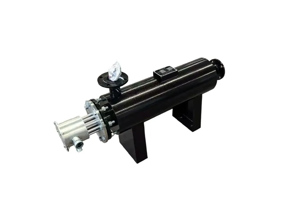
Engineering selection guide
Size from heat duty, not temperature alone.
A pipeline heater cannot be selected from target temperature or pipe diameter alone. The useful heating duty depends on how much medium flows through the system, how far its temperature must rise, how quickly that change is required and how much heat the pipework and equipment lose to the surroundings.
1. Confirm the medium and flow condition
First identify whether the medium is recirculating air, fresh process air, another gas or a liquid. Yigao's current pipeline heater product page describes a fan-driven electric air-heating configuration. If the project involves liquid, high pressure, corrosive gas or another medium, state that clearly so engineering does not apply air-heating reference data to the wrong duty.
- Medium: composition, humidity, dust, corrosiveness and cleanliness requirement.
- Flow: mass flow when available, or volume flow together with operating temperature and pressure.
- Temperature: minimum inlet, normal inlet, required outlet and maximum permitted temperature.
- Operation: once-through or recirculating, continuous or batch, and daily operating hours.
2. Estimate the useful heat duty
Use consistent engineering units. The formula calculates sensible heat added to the flowing medium; it does not by itself include duct heat loss, leakage, moisture evaporation, product heating or start-up of cold equipment.
3. Convert volume flow to mass flow at one reference condition
Volumetric airflow is only useful when its reference condition is known. Record whether the value is actual m³/h at the heater inlet, normal or standard m³/h, SCFM or another basis. For actual inlet flow, convert m³/h to m³/s and multiply by air density evaluated at the same inlet temperature, absolute pressure and humidity condition.
4. Check the calculation with a transparent example
Assume a verified dry-air mass flow of 0.40 kg/s, an inlet temperature of 30 °C, a required outlet temperature of 80 °C and a specific-heat assumption of 1.01 kJ/kg·K over that range. The illustrative useful duty is:
0.40 kg/s x 1.01 kJ/kg·K x (80 − 30) K = 20.2 kW.
This 20.2 kW value covers the stated sensible air-temperature rise only. Final installed power must separately account for verified system losses, start-up duty and control range. The density, specific heat and flow basis must be recalculated for the real medium and operating condition; this example is not a model recommendation.
5. Cross-check maximum temperature rise at minimum flow
After a provisional power is selected, rearrange the same relationship to estimate temperature rise at normal and minimum permitted mass flow: temperature rise = useful power ÷ (mass flow x specific heat). If the fan slows, a filter blocks or a damper closes, the same power can create a much higher outlet temperature. Define the minimum operating flow, power-stage limit and independent over-temperature response before finalizing controls.
6. Define the operating envelope, not one design point
7. Check pressure drop and airflow protection
The selected fan or circulation system must move the required flow through the heater, duct, filters and production equipment. Excessive resistance can reduce flow and create local overheating. Provide available fan pressure, duct route, bends, filters, damper positions and allowable pressure drop. An airflow or low-flow interlock should be considered so heating power cannot operate without sufficient circulation.
8. Match material, flange and element design
Carbon steel or stainless steel may be reviewed according to temperature, corrosion, humidity, cleanliness and cost. The drawing should define inlet and outlet direction, flange standard, support position, drain point, sensor location, maintenance clearance, junction box direction and insulation requirements.
9. Confirm control and electrical conditions
- Supply voltage, frequency, phase and available electrical capacity.
- Required control accuracy and acceptable outlet-temperature fluctuation.
- Staged contactor, SSR or thyristor control requirement.
- Main sensor, independent over-temperature sensor and downstream process sensor positions.
- PLC communication, remote start, alarm output and emergency stop requirements.
10. Quotation and calculation checklist
Send medium composition, minimum/normal/maximum flow with units and reference condition, inlet and outlet temperature range, operating pressure, available fan pressure, allowable pressure drop, recirculation ratio, duct and flange drawing, voltage, control requirement, installation environment, destination country, required standards and quantity. Identify how each design value was obtained and which assumptions still require measurement. If replacing an existing heater, include its power, dimensions, operating problems, available commissioning readings and site photos.
Buyer FAQ
Pipeline heater sizing FAQ
How is pipeline heater power estimated?
Start with medium mass flow, specific heat, inlet temperature and target outlet temperature. The basic heat duty is mass flow multiplied by specific heat and temperature rise, then heat loss, operating margin and control strategy must be reviewed. Final power should be confirmed from the real process data rather than selected from temperature alone.
Is air volume required when selecting an air pipeline heater?
Yes. Air volume or mass flow is essential because it determines how much medium must be heated each hour. Also provide inlet temperature, target outlet temperature, pressure or fan condition, duct size and whether the system recirculates air.
Can the 6–600 kW and ambient-to-800 °C ranges be used for every project?
No. They are reference ranges shown for the current Yigao pipeline heater product family. The achievable outlet temperature and power depend on airflow, heat loss, material, element loading, pressure, control method and installation conditions.
Should stainless steel or carbon steel be selected?
Material selection depends on temperature, humidity, corrosion, cleanliness requirements, pressure and the working environment. State the medium and operating conditions so the shell, flange, element and insulation materials can be reviewed together.
What protection should a pipeline heater include?
Typical items to review include independent over-temperature protection, airflow or low-flow interlock, staged power control, sensor placement, pressure monitoring when applicable, grounding and emergency stop logic. The required protection must match the process and local electrical rules.
How is air volume converted to mass flow for heater sizing?
Convert the stated volume flow to cubic metres per second, then multiply it by air density at the same temperature, pressure and humidity condition. Do not combine standard or normal volume flow with actual hot-air density without converting both to one reference condition. Record the original units and reference condition with the calculation.
Can fan motor power be used to size a pipeline heater?
No. Fan motor power does not establish the delivered mass flow because the fan curve, system resistance, duct, filter, damper and operating point also affect airflow. Use measured or design flow at the heater together with inlet temperature, target outlet temperature and pressure data.
Why must heater power be checked at minimum airflow?
The same electrical power produces a larger air-temperature rise when mass flow falls. Check the lowest permitted operating flow, staged-power or modulating limit, over-temperature protection and airflow interlock so the heater cannot apply excessive power when circulation is inadequate.